How to Improve Signal with High Pass Filters
2026-04-24
200
Catalog
Figure 1. High Pass Filter Signal Processing Visualization
What Is a Passive High Pass Filter and How Does It Work?
A passive high pass filter is a simple circuit that lets high-frequency signals pass while reducing low-frequency signals. It is called passive since it uses only a resistor and a capacitor, without any external power. The capacitor plays the main role: it blocks low-frequency signals but allows high-frequency signals to pass more easily. In a typical RC setup, the capacitor is in series with the input, and the resistor is connected to ground, with the output taken across the resistor. As the signal frequency increases, the capacitor offers less resistance, so more of the signal appears at the output. The point where the filter starts passing signals effectively is called the cut-off frequency:
Below this frequency, signals are weakened, while above it, they pass through more clearly. These filters are used in audio and signal circuits to remove low-frequency noise and improve signal quality.
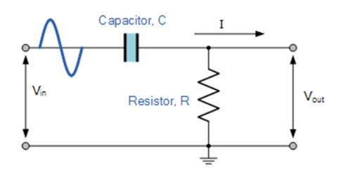
Figure 2. Passive RC High Pass Filter Circuit Diagram
How Frequency Affects a High Pass Filter
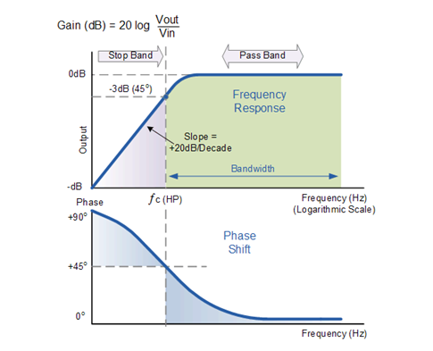
Figure 3. Frequency Response of a First-Order High Pass Filter
The behavior of a high pass filter depends on the input signal’s frequency. At low frequencies, the capacitor has high reactance, so it limits the signal and only a small output appears. As the frequency increases, the capacitor’s reactance decreases, allowing more current to pass and increasing the output voltage.
This can be seen in the frequency response (Bode plot), where the output rises at about +20 dB per decade (6 dB per octave) until it reaches the cut-off frequency. At this point, the output is about 70.7% of the input (−3 dB), marking the transition from attenuation to effective signal passing. At higher frequencies, most of the signal passes through with minimal loss.
The filter also affects phase. The output signal leads the input, with a phase shift of about +45° at the cut-off frequency, and it approaches 0° at higher frequencies. In theory, the filter can pass very high frequencies, but in actual circuits, performance is limited by the components used.
What Is Cut-off Frequency and Phase Shift
The cut-off frequency defines the point where a high pass filter transitions from attenuating to passing signals. At this frequency, the output is about 70.7% of the input (−3 dB). For a simple RC high pass filter, it is calculated using the standard RC formula.
The filter’s gain depends on frequency and can be expressed as:
where the capacitive reactance is:
As frequency increases, Xc decreases, allowing more signal to pass to the output.
The filter also introduces a phase shift. In a high pass filter, the output signal leads the input. At the cut-off frequency, the phase shift is about +45°, and it gradually approaches 0° at higher frequencies.
Step-by-Step High Pass Filter Calculation
To calculate the cut-off frequency of a high pass filter, you need the resistor and capacitor values. For example, R = 240 kΩ and C = 82 pF, the cut-off frequency can be found using:
Substituting the values into the formula gives a result of approximately 8,087 Hz, which can be rounded to 8.09 kHz (or about 8 kHz). This means signals above this frequency will pass more easily, while lower-frequency signals will be reduced.
Applications of High Pass Filters
Audio Systems - Used to eliminate low-frequency noise or hum, improving sound clarity in speakers and amplifiers.
Microphones - Helps reduce background rumble, wind noise, and handling noise in recording systems.
Signal Processing - Removes low-frequency interference and cleans signals before further processing.
Communication Systems - Filters out unwanted low-frequency noise to improve signal transmission quality.
Sensor Circuits - Used in sensors to focus on rapid changes or high-frequency signals, such as vibration or motion detection.
RF and Electronics Circuits - Blocks DC components while allowing AC signals to pass, protecting sensitive components.
Power Supply Filtering - Removes low-frequency ripple and stabilizes signal paths.
Biomedical Signals - Filters baseline drift in ECG or EEG signals to highlight important changes.
Image Processing - Enhances edges and fine details by removing low-frequency components.
Instrumentation Systems - Improves measurement accuracy by eliminating slow signal variations.
Second-Order High Pass Filter and Why It Is Used
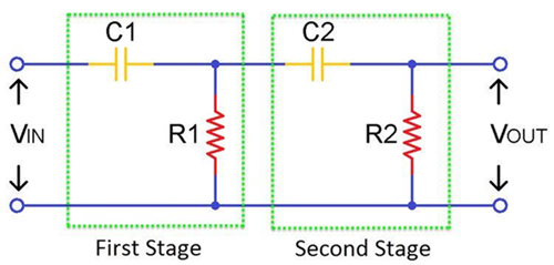
Figure 4. Second-Order Passive High Pass Filter
A second-order high pass filter is an improved version of a basic high pass filter that provides a sharper and more effective separation between low- and high-frequency signals. It is typically formed by combining two first-order filter stages, which increases the filtering performance.
Compared to a first-order filter, a second-order design has a steeper roll-off of −40 dB per decade (12 dB per octave). This means it reduces unwanted low-frequency signals much faster, making it more suitable for applications that require cleaner signal output.
Passive RC Differentiator
A passive RC differentiator is a simple high pass filter circuit that produces an output proportional to the rate of change of the input signal. It uses only a resistor and a capacitor, making it a basic and low-cost design. Unlike standard high pass filters used for general filtering, a differentiator is specifically used to highlight rapid changes in a signal, such as edges or spikes.
How an RC Differentiator Circuit Works
In an RC differentiator, the capacitor is connected in series with the input signal, and the resistor is connected to ground, with the output taken across the resistor. When the input signal changes quickly, the capacitor allows a brief current to flow, producing a sharp voltage across the resistor. If the input signal is constant or changes slowly, very little current flows, resulting in a very small output.
For proper differentiation, the circuit is designed so that the time constant (RC) is much smaller than the signal period. This condition allows the output to closely follow the derivative of the input waveform:
High Pass Filter vs Low Pass Filter
High pass and low pass filters are basic circuits used to control how signals pass based on their frequency. The main difference is how they treat low and high frequencies.
A high pass filter allows high-frequency signals to pass while reducing low-frequency signals. In contrast, a low pass filter allows low-frequency signals to pass while reducing high-frequency signals. This makes them useful for different purposes depending on the application.
|
Feature |
High
Pass Filter |
Low
Pass Filter |
|
Function |
Passes high
frequencies |
Passes low
frequencies |
|
Blocks |
Low-frequency signals |
High-frequency
signals |
|
Capacitor Behavior |
Blocks low frequency,
passes high |
Passes low frequency,
blocks high |
|
Output at Low
Frequency |
Very low |
High |
|
Output at High
Frequency |
High |
Very low |
|
Common Use |
Remove noise, detect
changes |
Smooth signals,
reduce noise |
How to Choose the Right High Pass Filter for Your Circuit
Identify the signal range - Determine the useful signal frequencies you want to keep and the low-frequency noise you want to remove.
Set the cut-off point - Place the cut-off just below the lowest useful signal so important signals pass while unwanted ones are reduced.
Choose the filter order:
First-order → simple and suitable for basic filtering
Second-order → better for stronger filtering and sharper signal separation
Decide between passive and active:
Passive filter → simple, no power needed, but may reduce signal strength
Active filter → uses an op-amp, provides gain, and offers better control
Consider component values - Select appropriate resistor and capacitor values to match your target frequency range.
Check actual factors - Account for component tolerance, noise, and signal level to ensure stable performance.
Match the application - Choose the filter based on where it will be used, such as audio systems, sensors, or communication circuits.
How Signal Quality and Phase Shift Affect Signal Output
Signal quality in a high pass filter is directly influenced by how the circuit handles different frequencies. Low-frequency components, including unwanted noise such as hum or drift, are reduced, which helps produce a cleaner output signal. At the same time, high-frequency signals pass through more effectively with minimal loss. However, near the cut-off region, the signal amplitude is partially reduced, which can slightly weaken the output if the filter is not properly designed.
Along with changes in amplitude, a high pass filter also introduces a phase shift, meaning the output signal does not occur at exactly the same time as the input. The output typically leads the input signal, with the phase difference being larger at low frequencies and gradually decreasing as the frequency increases. At higher frequencies, the output becomes more aligned with the input. These effects are required in actual applications, as both signal quality and timing can impact performance in audio systems, communication circuits, and measurement systems.
How to Fix Noise or Signal Loss in High Pass Circuits
Check the cut-off setting - If the cut-off is too high, useful signal gets attenuated. Lower it so your desired frequencies pass clearly.
Use correct component values and quality parts - Choose accurate resistor and capacitor values, and use low-tolerance, stable components (e.g., film capacitors) to reduce variation and noise.
Improve grounding and layout - Keep ground paths short and clean, avoid ground loops, and place components close together to reduce interference.
Minimize parasitic effects - Long wires and poor PCB layout add unwanted resistance and capacitance. Use short traces and proper routing.
Add buffering (if needed) - Use a buffer or op-amp stage to prevent loading, especially when the next stage draws current and weakens the signal.
Shield against external noise - Use shielding, twisted wires, or proper enclosure to reduce electromagnetic interference (EMI).
Check signal source and load impedance - Mismatch can cause signal loss. Ensure the source and load are compatible with the filter design.
Use proper power supply filtering (for active filters) - Noise in the power supply can affect output. Add decoupling capacitors if using op-amps.
Conclusion
High pass filters play a big role in improving signal quality by reducing unwanted low-frequency components and allowing useful signals to pass. From basic RC circuits to more advanced second-order designs and differentiators, these filters are widely applied in many electronic systems. By understanding how they work, how to choose the right design, and how to fix common problems, you can apply high pass filters effectively in your circuits and achieve better performance in your applications.
function test. The highest cost-effective products and the best service is our eternal commitment.
Hot Article
- LM358 Dual Operational Amplifier Comprehensive Guide: Pinouts, Circuit Diagrams, Equivalents, Useful Examples
- Are CR2032 and CR2016 Interchangeable?
- Understanding the Differences ESP32 and ESP32-S3 Technical and Performance Analysis
- Choosing the Right Battery: A Guide to AG4, LR626, LR66, 177/376/377, SR626, and SR626SW Equivalents
- NPN vs. PNP: What's the Difference?
- BC547 Transistor Basics: Pinout, Application Circuits, Alternative/Complementary Models
- esp32 vs stm32: which microcontroller is better for you?
- What Is a MOSFET and How It Works?
- Electrical Relay Basic: Working Operation, Types and Uses
- PNP Transistors: Structure, Working Principle and Application
 Ceramic vs Electrolytic Capacitors: Choosing the Right One for Your Circuit
2026-04-24
 ASIC vs FPGA: Which One Should You Choose?
2026-04-24
Frequently Asked Questions [FAQ]
1. Why is a capacitor used in a high pass filter?
A capacitor is used as its behavior depends on frequency. It blocks low-frequency signals while allowing high-frequency signals to pass, making it essential for separating unwanted low-frequency components.
2. Can a high pass filter block DC signals?
Yes, a high pass filter blocks DC signals completely as DC has zero frequency. Since the capacitor cannot pass a constant signal, it prevents DC from reaching the output.
3. What happens if the cut-off frequency is set too high?
If the cut-off frequency is too high, useful parts of the signal may be reduced or lost. This can weaken the output and remove important information from the signal.
4. What happens if the cut-off frequency is too low?
If the cut-off frequency is too low, unwanted low-frequency noise may still pass through. This can reduce the effectiveness of the filter in cleaning the signal.
5. Is a high pass filter the same as a differentiator?
No, a differentiator is a special type of high pass filter designed to respond to rapid changes in a signal. While both use similar components, their design and purpose are slightly different.
Hot Part Number
 C0402X6S0G331K020BC
 GRT31CR61E475KE01L
 GR442QR73D221KW01L
 GRM0335C1E2R7CA01J
- GRM033R71E332KA12J
 EMK063B7682KP-F
 CS1206KKX7RYBB473
 LD02YC181KAB2A
 12105C154KHT1A
 1812GA221JAT9A
- T495X336M025AHE200
- DSI30-12A
- SI6975DQ-T1-E3
- SL38160AZC-18AHT
- MAX3232EEUE+T
- MT48LC4M16A2P-6:G
- MAX6356TWUT+T
- LCMXO1200C-5FTN256C
- FP15R12KT3
- LTC3638IMSE#PBF
- T491A474M025AT7622
- TMS320C6455BCTZ7
- T491D106K035AH2478
- T491X226M035ATAUTO
- T491C475M035ZTAU00
- ST7FLITE02Y0M6
- LT4256-1IS8#PBF
- LM2594MX-5.0/NOPB
- GE212JIYJ23JB
- GE28F256L18B
- HD64F2329BVTE25
- ICS93722CF
- IS61LPS51236A-200TQL
- KSZ8841PMQL
- MT41K256M16TW-107IT:P
- MT49H16M18CFM-5IT
- P51XAG37KBBD
- ST19NP18ER28PVMX
- STPR1020CTW
- AK4311AVM-E2
- LR36A11A
- NAT7210BPD
- IH5047MJE/883B
- MAX232MJE/883
- MM3Z2V4S
- GS8662Q18BGD-300
- AD8876ACPZ
- WL2851E33-5/TR
- BM05B-PASS-TF