Ceramic vs Electrolytic Capacitors: Choosing the Right One for Your Circuit
2026-04-24
224
Catalog
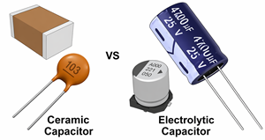
What Is a Ceramic Capacitor?
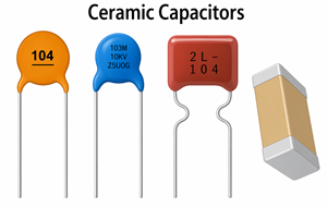
Figure 2. Types or Examples of Ceramic Capacitors
Ceramic capacitors are compact, fast, and widely used in high-frequency circuits. They use a ceramic material as the dielectric and often feature multilayer structures to increase capacitance while keeping size small.
Ceramic capacitors are non-polarized and easy to install. They have low ESR and ESL, which allows fast response and excellent high-frequency performance. They also offer long lifespan and compact size, making them ideal for modern electronics.
Ceramic capacitors are divided into two main classes. Class 1 capacitors provide high stability and accuracy, which makes them suitable for precision applications. Class 2 capacitors offer higher capacitance but with moderate stability, making them suitable for general-purpose use.
Capacitance in ceramic capacitors can decrease when a DC voltage is applied. This DC bias effect is common in Class 2 capacitors and must be considered during design.
Ceramic capacitors are commonly used for decoupling ICs, noise filtering, RF ceffective decoupling near ICsircuits, high-speed digital systems, and timing applications.
What Is an Electrolytic Capacitor?
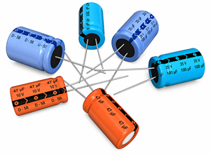
Figure 3. Electrolytic Capacitors in Different Sizes
Electrolytic capacitors are designed for high capacitance and energy storage. They are widely used in power supplies and low-frequency applications.
They use a thin oxide layer as the dielectric and an electrolyte as part of the conductive structure. This design increases the effective surface area, allowing high capacitance in a relatively compact size. Typical values range from microfarads to thousands of microfarads.
Electrolytic capacitors provide high capacitance and use a polarized design, so correct connection is required. They have higher ESR and ESL compared to ceramic capacitors, a limited lifespan, and are best suited for low-frequency use.
These capacitors degrade over time, and heat or ripple current can accelerate this process. Despite this, they remain widely used because of their ability to store large amounts of energy.
Common applications include power supply filtering, voltage ripple reduction, bulk energy storage, audio circuits, and DC stabilization.
Ceramic vs Electrolytic Capacitors
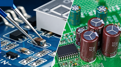
Figure 4. Ceramic vs Electrolytic Capacitors in Circuits
|
Feature |
Ceramic |
Electrolytic |
|
Capacitance |
Low to moderate |
High |
|
Polarity |
Non-polarized |
Polarized |
|
ESR |
Low |
Higher |
|
Best for |
High-frequency applications |
Low-frequency / power use |
|
Lifespan |
Long |
Limited |
|
Physical size |
Compact |
Larger |
Ceramic capacitors respond quickly to voltage changes and are highly effective at filtering high-frequency noise. Electrolytic capacitors provide large energy storage and are better suited for smoothing voltage in power systems.
Pros and Cons
Ceramic Capacitors
Ceramic capacitors are non-polarized, compact, and highly efficient at high frequencies. They offer low energy loss, long lifespan, and stable performance, especially in Class 1 types. However, they have limited capacitance, higher cost at large values, and may experience capacitance reduction under voltage. Some types may produce audible noise (microphonics) in sensitive circuits.
Electrolytic Capacitors
Electrolytic capacitors provide high capacitance at a lower cost, making them ideal for energy storage and power filtering. They are widely available and effective for low-frequency applications. However, they are polarized, have limited lifespan, higher ESR, and reduced performance at high frequencies.
When to Use Each Capacitor?
Use ceramic capacitors for high-frequency filtering, fast transient response, and decoupling near ICs. Their low ESR and small size make them ideal for placement close to sensitive components in high-speed circuits.
Use electrolytic capacitors for power supply filtering, voltage ripple reduction, and bulk energy storage. They are best suited for low-frequency applications where large capacitance values are required.
In most designs, both are used together. For example, in a phone charger, an electrolytic capacitor smooths the main power supply, while ceramic capacitors filter high-frequency noise near the control chips.
Power Supply Filtering and Decoupling
Ceramic capacitors are placed close to IC power pins to reduce noise and voltage spikes, providing fast response to high-frequency changes.
Electrolytic capacitors are placed on power rails to smooth low-frequency ripple and stabilize the supply, typically using values from 100 µF to 4700 µF or higher.
Together, they provide stable and clean power across the circuit.
Practical Capacitor Circuit Examples
In practical designs, ceramic and electrolytic capacitors are often used together to handle both high-frequency noise and low-frequency stability. Each type serves a different purpose in maintaining circuit stability and reliability.
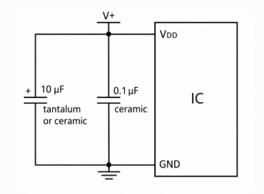
Figure 5. MCU Decoupling: 0.1µF + 10µF Capacitors
1. MCU Power Supply Decoupling Circuit
Components:
• 0.1µF ceramic capacitor placed close to the MCU power pins
• 10µF electrolytic capacitor placed on the supply line
Why:
• The ceramic capacitor filters high-frequency noise caused by fast switching inside the MCU
• The electrolytic capacitor provides bulk energy to stabilize the supply during voltage dips
Place the 0.1µF capacitor as close as possible to the MCU power pin to minimize noise and trace inductance.
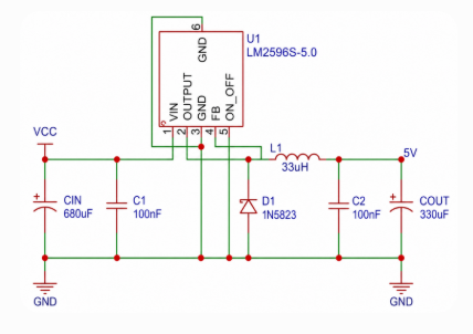
Figure 6. DC-DC Converter with Input and Output Filtering Capacitors
2. DC-DC Converter Input Filtering Circuit
Components:
• Bulk capacitor (electrolytic, typically 47–470µF)
• Ceramic capacitor (typically 0.1µF–1µF)
Why:
• The bulk capacitor smooths input voltage ripple and supports sudden load changes
• The ceramic capacitor filters high-frequency switching noise from the converter
Place the ceramic capacitor close to the converter input pins and the bulk capacitor slightly farther on the input line for best performance.
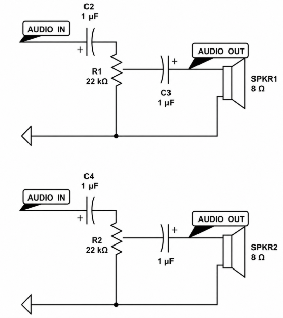
Figure 7. Audio Coupling Circuit using Capacitors for Signal Filtering
3. Audio Signal Coupling Circuit
Components:
• Electrolytic capacitor (typically 1µF–100µF) placed in series with the signal path
Why:
• Blocks DC voltage while allowing the AC audio signal to pass
• Ensures clean signal transmission without DC offset
This capacitor forms a high-pass filter with the input resistance.
Choose a higher capacitance value to preserve low-frequency signals and prevent audio signal loss.
Conclusion
Ceramic and electrolytic capacitors complement each other in circuit design. Ceramic capacitors respond quickly to high-frequency changes, while electrolytic capacitors support voltage stability and energy storage. Using them correctly and placing them in the right locations improves overall circuit behavior and efficiency. The right combination leads to more consistent and reliable performance in practical applications.
function test. The highest cost-effective products and the best service is our eternal commitment.
Hot Article
- LM358 Dual Operational Amplifier Comprehensive Guide: Pinouts, Circuit Diagrams, Equivalents, Useful Examples
- Are CR2032 and CR2016 Interchangeable?
- Understanding the Differences ESP32 and ESP32-S3 Technical and Performance Analysis
- Choosing the Right Battery: A Guide to AG4, LR626, LR66, 177/376/377, SR626, and SR626SW Equivalents
- NPN vs. PNP: What's the Difference?
- BC547 Transistor Basics: Pinout, Application Circuits, Alternative/Complementary Models
- esp32 vs stm32: which microcontroller is better for you?
- What Is a MOSFET and How It Works?
- Electrical Relay Basic: Working Operation, Types and Uses
- PNP Transistors: Structure, Working Principle and Application
 Class X vs Class Y Capacitors: What’s the Difference?
2026-04-25
 How to Improve Signal with High Pass Filters
2026-04-24
Frequently Asked Questions [FAQ]
1. How do switching circuits influence capacitor selection?
Switching circuits generate high-frequency noise, requiring low-ESR ceramic capacitors for fast response, combined with electrolytic capacitors for stability and energy storage.
2. Why are ceramic capacitors always placed close to IC power pins?
Placing them close reduces trace inductance and allows faster response to high-frequency noise, improving decoupling efficiency and circuit stability.
3. How do ceramic and electrolytic capacitors work together in power supply filtering?
Ceramic capacitors handle high-frequency noise, while electrolytic capacitors smooth low-frequency ripple and provide bulk energy. Together, they ensure stable and clean power.
4. What happens if you only use electrolytic capacitors without ceramic capacitors?
The circuit may suffer from high-frequency noise and voltage spikes, since electrolytic capacitors respond too slowly to fast changes.
5. Why do electrolytic capacitors have a shorter lifespan compared to ceramic capacitors?
Electrolytic capacitors degrade due to electrolyte evaporation and heat, which increases ESR and reduces performance over time.
6. Why are electrolytic capacitors preferred for bulk energy storage?
Their design provides very high capacitance in a small size, making them effective for handling voltage drops and load changes in power systems.
7. What design mistakes can reduce capacitor effectiveness in a circuit?
Common mistakes include placing capacitors too far from components, ignoring DC bias effects, and using incorrect capacitance or voltage ratings.
Hot Part Number
 GQM2195C2A5R6CB01D
 CGA5L1X7R1C685K160AC
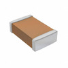 CL10C020CB8NNND
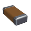 12063A681JAT2A
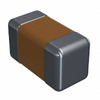 04023A3R0BAT2A
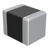 LMK325BJ335MD-T
 CGA5C2C0G1H822J060AD
 12102U151JAT2A
 T491D226M035AT
 T494X476K035AH
- EP1K50TC144-3N
- ATTINY13V-10SSU
- FT232HQ-TRAY
- PIC12F609T-I/SN
- RT0603DRE07360KL
- RC0805FR-07130RL
- B43586-S9418-Q1
- V24C28T100AL
- STM32F765NIH6
- MC74AC240DW
- NTF5P03T3G
- TMP275AIDGKTG4
- S8VK-C12024
- T491B157M006AH
- XC5VFX70T-1FF665C
- LM4819MM/NOPB
- ADP3335ARMZ2.5
- DM74ALS244AWX
- FFPF06F20DNTU
- HC55142IB
- ICS525-01RLF
- K4X56323PI-8GC6
- LTC1665CGN
- OXUF943SE-LQAG
- PEF3452HV1.3
- STM32F100CBT6
- WM8718SEDS
- GL256P11FFIV1
- H5PS5162FR-Y5C
- LC67F5006AU-TQFP
- NPX5410-BB1C
- ST92T163T1
- ELJRF3N3DFB
- S29GL128M10TDIR21
- MT48LC8M32LFB5-10IT
- SC550349MFU42L16N
- MSM83C154BP-486JS-G
- STC10F12XE-35I-LQFP44
- HD6417020TE20I