The Ultimate Guide to LM317 Transformers: Data, Characteristics, and Their Applications
2023-12-01
7417
Catalog
The LM317 is a voltage regulator chip frequently used in circuits, noted for its variable output voltage. This linear regulator is apt for a vast range of electronic applications, such as power circuits, analog circuits, and precision instruments. The LM317 delivers a stable output voltage by managing the difference between input and output, featuring commendable load and line regulation.
What is LM317?
The LM317 is a three-terminal adjustable regulator employing a fixed internal reference voltage, allowing for output voltage adjustment via external resistors. It's commonly utilized in various power circuits as a regulator, providing a stable voltage output and effectively shielding subsequent circuits from input voltage fluctuations.
Pinout of the LM317
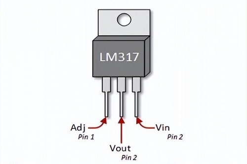
Figure 1: LM317 Pinout
Looking at the voltage regulator from the front, the first pin on the left is ADJ, the middle one is Vout, and the last pin on the right is Vin.
Input (Vin): Vin is the pin that receives the input voltage, which will be regulated to a specific voltage.
Output (Vout): Vout is the pin that provides a stable output. It delivers an adjustable voltage, typically connected to circuits that require voltage regulation.
Adjustment (ADJ): ADJ is the pin that allows for control over the voltage output. This pin is usually connected to a resistor in conjunction with the output pin to set the desired output voltage.
Characteristics of the LM317
Output Voltage Range: Adjustable from 1.25V to 37V.
Output Capacity: Capable of delivering 1.5A of output current.
Input-Output Voltage Differential: Maximum of 40V, but a recommended differential is 3V to 15V for optimal regulation stability.
Maximum Output Current at 15V Differential: 2.2A.
Thermal Stability: Remains stable within a temperature range of 0 to 125°C.
Packaging: Commonly available in To-220, SOT223, and To-263, among others.
Load Regulation: Typically at 0.1%.
Line Regulation: Typically at 0.01%/V.
Ripple Rejection Ratio: 80 dB.
Adjustment Pin Current: Typical values range from 50μA to 100μA.
Over-Temperature Protection: Features thermal shutdown to prevent damage due to overheating.
Short-Circuit Protection: Includes internal current limiting for short-circuit conditions.
Principle of operation of LM317
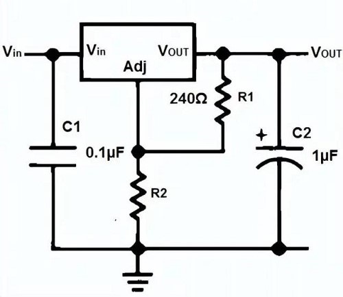
Figure 2: LM317 Working Principle
The working principle of the LM317 revolves around maintaining a constant voltage drop across two pins. It has a fixed internal reference voltage, typically 1.25 volts, which serves as the benchmark for adjusting the output voltage of the regulator. By varying the resistance value of R2, the voltage between the Vout and ADJ terminals can be altered, thereby changing the output voltage at Vout. The presence of capacitors C1 and C2 ensures the circuit's stable operation, reducing voltage fluctuations and noise. By precisely selecting the values for R1 and R2, users can set the desired output voltage anywhere from 1.25 volts up to several tens of volts during usage.
This is the advantage of an adjustable voltage regulator; you can tune it to any voltage within the regulator's supported range.
Note: Capacitors C1 and C2 are used for power line cleanup. C1 is optional and typically used for transient response cleanup. However, C2 is necessary when the device is distant from any filtering capacitors, as it helps smooth out the power lines in the event of current spikes.
Resistance/Voltage Calculation for LM317
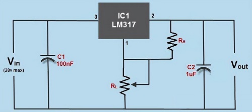
Figure 3: LM317 Voltage Calculation Chart
You can use the following formula to calculate the output voltage (Vout), which is dependent on the values of external resistors R1 and R2.
Vout = 1.25V (1 + R2/R1)
Typically, the value of R1 is fixed at 240 ohms (recommended), but it can also be set between 100 and 1000 ohms. Then, you must input the value of R2 to perform the output voltage calculation. In this case, if R2 is using 1000 ohms, the formula completes as follows:
Vout=1.25X(1+1000/240)=6.453V
Similarly, you can calculate the value of R2 using the same formula. If you have set your output voltage to 10V, then you can calculate the value of R2 as follows:
10 = 1.25x(1 + R2/240)=> R2 = 1680Ω
Now let's look at an example of using the LM317:
The image below shows the LM317 regulator connected to a circuit, aiming to provide a stable DC voltage output for the circuit.
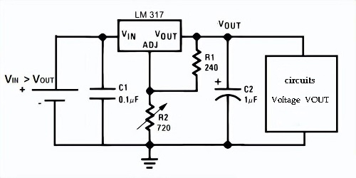
Figure 4: LM317 Case Circuit
In this circuit, we add a DC voltage source to the Vin pin of the regulator. This pin once again receives the input voltage, which the chip will regulate down. The voltage entering this pin must be higher than the voltage it outputs. However, note that the regulator only adjusts the voltage to a certain level; it does not and cannot generate voltage on its own. Thus, to achieve an output voltage Vout, Vin must be greater than Vout.
In this circuit, we need a stable 5VDC as the output, so Vin must be more than 5 V. Typically, unless it's a low-dropout regulator, you want the input voltage to be about 2V higher. Therefore, for a 5V output, we would feed 7 V into the regulator.
Having dealt with the input pin, we now move on to the adjustable pin (Adj). Since we desire a 5 V output, we must calculate which value of R2 will produce a 5 V output.
Using the output voltage formula:
Vout = 1.25V (1 + R2/R1)
Since R1 is 240 ohms, so:
5V = 1.25V (1 + R2/2402), so R2 = 720Ω
Therefore, with a value of R2 at 720 ohms, if you supply an input voltage greater than 5 V, LM317 will output 5V.
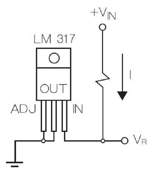
Figure 5: LM317 Wiring Diagram
The last pin of LM317 is the output pin, and to supply the circuit with the regulated 5 volts, we simply connect it to the output pin.
How to Use LM317
The LM317 component regulates a 1.25V difference between the output and adjustment pins. You can alter the output by using two resistors connected between the output and input pins.
Additionally, two decoupling capacitors can be integrated into the circuit. This setup helps eliminate unnecessary coupling and prevents noise.
A 1uF capacitor connected to the output improves the transient response. Furthermore, you can utilize it as a variable regulator by clicking a potentiometer onto the adjustable pin.
Resistors and potentiometers work together to create the potential difference necessary for regulated output.
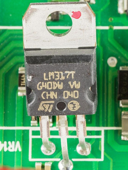
Figure 6: LM317 live circuit diagram
Equivalent ICs to LM317
Alternative models to LM317 include: LM7805, LM7806, LM7809, LM7812, LM7905, LM7912, LM117V33, and XC6206P332MR.
Equivalent models to LM317: LT1086, LM1117 (SMD), PB137, and LM337 (a negative variable voltage regulator).
How to Protect LM317 Circuit
Protecting an LM317 circuit is crucial to prevent damage. Due to increased power consumption, components might overheat during operation. For this reason, heat sinks are commonly used to protect the IC from overheating. Additionally, due to the low current of the transformer, external capacitors can discharge. Therefore, diodes are added in some applications to prevent capacitor discharge.
Diode D1 protects the capacitor from discharging during input short circuits, while diode D2 is used to provide a low-impedance discharge path to protect CAdj during output short circuits. To achieve a high ripple suppression ratio, bypass the ADJUST terminal.
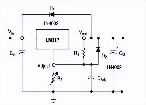
Figure 7: LM317 Protection Circuit Diagram
In summary, the LM317 is a commonly used voltage regulator chip that provides stable output voltage by controlling the difference between input and output. Its pinout and parameters help engineers correctly apply and configure this chip to achieve the desired power stability and reliability.
 ABOUT US
Customer satisfaction every time. Mutual trust and common interests.
function test. The highest cost-effective products and the best service is our eternal commitment.
Hot Article
- Are CR2032 and CR2016 Interchangeable
- MOSFET: Definition, Working Principle and Selection
- Relay Installation and Testing, Interpretation of Relay Wiring Diagrams
- CR2016 vs. CR2032 What’s the difference
- NPN vs. PNP: What's the Difference?
- esp32 vs stm32: which microcontroller is better for you?
- LM358 Dual Operational Amplifier Comprehensive Guide: Pinouts, Circuit Diagrams, Equivalents, Useful Examples
- CR2032 VS DL2032 VS CR2025 Comparison Guide
- Understanding the Differences ESP32 and ESP32-S3 Technical and Performance Analysis
- Detailed Analysis of RC Series Circuit
 7408 Logic Gate Chip Ultimate Guide: Pinout, Characteristics and Applications
2025-04-02
 Relay Installation and Testing, Interpretation of Relay Wiring Diagrams
2023-11-30
Hot Part Number
 CL21B274JOCNNNC
 CL31B222KGFNNNE
 GRM1885C1H821GA01J
 GCM1555C1H8R5DA16D
 GRM1885C1H2R7BA01J
 LD055A152JAB2A
 GRM0337U1H7R9CD01D
 T491C226M020AT
 T350E475M035AT7301
 TPSS105K020R6000
- BFP640ESDH6327XTSA1
- TLE6236G
- VE-242-IX
- TSC80251G2D-L16CB
- MT9042CP1
- VE-253-EY
- V48B2V2C100AL2
- MC74HCT595ADTR2G
- S29GL01GS11FHB023
- STM6519AUARUB6F
- T491V476M010AT
- T491A154K050AH
- OPA2340EA/250G4
- STFPC311BTR
- AD9983AKCPZ-170
- CS4208-CRZ
- DC213-B1
- EPM7256BTI144-7
- ICS843011AGLFT
- ICS9LPRS355BKL
- LE82GS965
- M28W640FCT70N6
- PSB2197TV1.1G
- S29JL032H70TFI21
- SST39VF040-70-4C-NH
- STAC9271D5PRG8
- STC12C5412AD-35I-SOP28G
- TC514402AZ-80
- TLV5623IDGKT
- W29C020P-90B
- XC18V02-PC44C
- MSP4448G
- P2003BVG
- SSS3N90A
- TSB12LV32
- GM2221-LF-BC
- H9CCNNNBPTMLBR-NTM
- N80C188EB13
- GRM21BZ71E475KE15L