Electrifying Insights: Mastering Silicon Controlled Rectifiers (SCRs)
2024-05-24
6196
Catalog
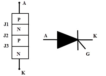
Figure 1: SCR Symbol and its Terminals
Silicon Controlled Rectifier Symbol
The Silicon Controlled Rectifier (SCR) symbol resembles a diode symbol but includes an additional gate terminal. This design highlights the SCR's ability to allow current to flow in one direction—from the Anode (A) to the Cathode (K)—while blocking it in the opposite direction. The three key terminals are:
Anode (A): The terminal where current enters when the SCR is forward-biased.
Cathode (K): The terminal where the current exits.
Gate (G): The control terminal that triggers the SCR.
The SCR symbol is also used for Thyristors, which have similar switching characteristics. Proper biasing and control methods depend on understanding the symbol. This foundational knowledge is essential before exploring the device's construction and operation, enabling effective use in various electrical circuits.
Silicon Controlled Rectifier Construction
The Silicon Controlled Rectifier (SCR) is a four-layer semiconductor device that alternates P-type and N-type materials, forming three junctions: J1, J2, and J3. Let's break down its construction and operation in detail.
Layer Composition
Outer Layers: The outer P and N layers are heavily doped with impurities to increase their electrical conductivity and reduce resistance. This heavy doping allows these layers to efficiently conduct high currents, enhancing the SCR's performance in managing large power loads.
Middle Layers: The inner P and N layers are lightly doped, meaning they have fewer impurities. This light doping is crucial for controlling current flow, as it enables the formation of depletion regions—areas within the semiconductor where mobile charge carriers are absent. These depletion regions are key in controlling the flow of current, allowing the SCR to function as a precise switch.
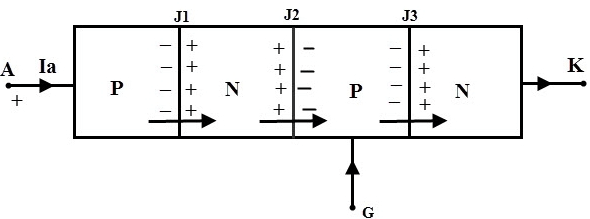
Figure 2: P and N Layer of SCR
Terminal Connections
Gate Terminal: The gate terminal connects to the middle P-layer. Applying a small current to the gate triggers the SCR, allowing a larger current to flow from the anode to the cathode. Once triggered, the SCR remains on even if the gate current is removed, provided there's sufficient voltage between the anode and cathode.
Anode Terminal: The anode terminal connects to the outer P-layer and serves as the entry point for the main current. For the SCR to conduct, the anode must be at a higher potential than the cathode, and the gate must receive a triggering current. In the conducting state, current flows from the anode through the SCR to the cathode.
Cathode Terminal: The cathode terminal connects to the outer N-layer and acts as the exit point for the current. When the SCR is conducted, the cathode ensures current flows in the correct direction, from the anode to the cathode.
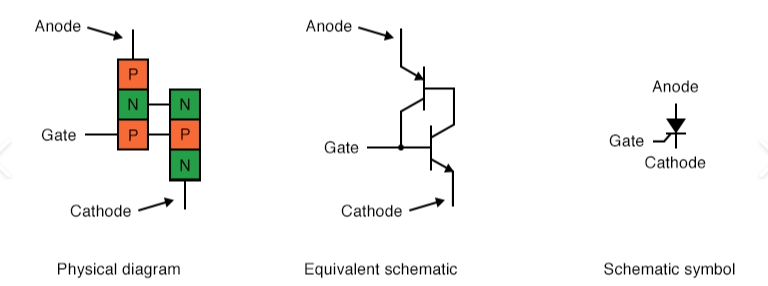
Figure 3: The Gate, Anode, and Cathode Terminal
Material Choice
Silicon is preferred over germanium for SCR construction due to several advantages:
Lower Leakage Current: Silicon has a lower intrinsic carrier concentration, resulting in reduced leakage currents. This is essential for maintaining efficiency and reliability, particularly in high-temperature environments.
Higher Thermal Stability: Silicon can operate at higher temperatures than germanium, making it more suitable for high-power applications where significant heat is generated.
Better Electrical Characteristics: With a wider bandgap (1.1 eV for silicon vs. 0.66 eV for germanium), silicon offers better electrical performance, such as higher breakdown voltages and more robust operation under various conditions.
Availability and Cost: Silicon is more abundant and cheaper to process than germanium. The well-established silicon industry allows for cost-effective and scalable manufacturing processes.
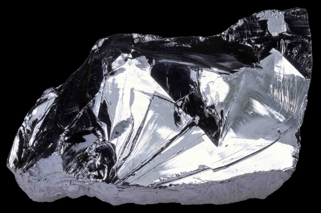
Figure 4: Silicon
How about Germanium?
Germanium has several drawbacks compared to silicon, making it less suitable for many applications. Germanium cannot withstand high temperatures as effectively as silicon. This limits its use in high-power applications where significant heat is generated. Then, germanium has a higher intrinsic carrier concentration, resulting in higher leakage currents. This increases power loss and reduces efficiency, particularly in high-temperature conditions. In addition to this, germanium was used in the early days of semiconductor devices. However, its limitations in thermal stability and leakage current led to the widespread adoption of silicon. Silicon's superior properties have made it the preferred material for most semiconductor applications.
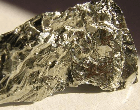
Figure 5: Germanium
Types of SCR Construction
Planar Construction
Planar construction is best for devices that handle lower power levels while still providing high performance and reliability.
In planar construction, the semiconductor material, typically silicon, undergoes diffusion processes where impurities (dopants) are introduced to form p-type and n-type regions. These dopants are diffused in a single, flat plane, resulting in a uniform and controlled formation of junctions.
The advantages of planar construction include creating a uniform electric field across the junctions, which reduces potential variations and electrical noise, thereby improving the device’s performance and reliability. Since all junctions are formed in a single plane, the manufacturing process is streamlined, simplifying the photolithography and etching steps. This not only reduces complexity and cost but also improves yield rates by making it easier to consistently control and reproduce the necessary structures.

Figure 6: Planar SCR Process
Mesa Construction
Mesa SCRs are built for high-power environments and are commonly used in industrial applications such as motor control and power conversion.
The J2 junction, the second P-N junction in an SCR, is created using diffusion, where dopant atoms are introduced into the silicon wafer to form the necessary P-type and N-type regions. This process allows for precise control over the junction's properties. The outer P and N layers are formed through an alloying process, where a material with the desired dopants is melted onto the silicon wafer, creating a robust and durable layer.
The advantages of mesa construction include its ability to manage high currents and voltages without degrading, thanks to the robust junctions formed by diffusion and alloying. The strong and durable design enhances the SCR's capacity to handle large currents efficiently, making it reliable for high-power applications. Additionally, it is suitable for various high-power applications, providing a versatile choice for different industries.
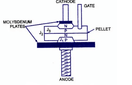
Figure 7: Mesa SCR Process
External Construction
External construction of SCRs focuses on durability, effective thermal management, and ease of integration into power electronics. The anode terminal, typically a larger terminal or tab, is designed to handle high currents and is connected to the positive side of the power supply. The cathode terminal, connected to the negative side of the power supply or load, is also designed for high-current handling and is marked. The gate terminal, used to trigger the SCR into conduction, is usually smaller and requires careful handling to avoid damage from excessive current or voltage.
The advantages of SCRs in external construction include their suitability for industrial applications such as motor controls, power supplies, and large rectifiers, where they manage power levels beyond many other semiconductor devices. Their low on-state voltage drop minimizes power dissipation, making them ideal for energy-efficient applications. The simple triggering mechanism via the gate terminal allows for easy integration into control circuits and systems. Furthermore, their widespread availability and mature manufacturing processes contribute to their cost-effectiveness.
In summary, when using these different types of SCR structures, the appropriate SCR structure can be selected for different situations.
Planar Construction: Ideal for low-power applications. It is necessary in circuits that require electrical noise reduction and consistent performance.
Mesa Construction: For high-power applications, pay attention to the heat dissipation needs and robust design requirements. Ensure that the SCR can handle the expected current and voltage levels without overheating.
External Construction: Handle the terminals carefully, especially the gate terminal. Make sure connections are secure and designed to manage high current flows efficiently.
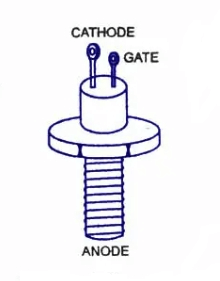
Figure 8: External Construction Process
Operational Insights
The four-layer structure of an SCR forms an NPNP or PNPN configuration, creating a regenerative feedback loop once triggered, which maintains conduction until the current falls below a specific threshold. To trigger the SCR, apply a small current to the gate terminal, initiating the breakdown of the J2 junction and allowing current to flow from the anode to the cathode. Effective heat management is important for high-power SCRs, and using press pack construction with a robust heat sink connection ensures efficient heat dissipation, preventing thermal runaway and enhancing the device's longevity.
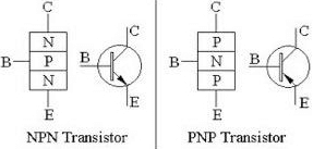
Figure 9: NPN and PNP
Primary Modes of Silicon Controlled Rectifier
The Silicon Controlled Rectifier (SCR) operates in three primary modes: Forward Blocking, Forward Conduction, and Reverse Blocking.
Forward Blocking Mode
In Forward Blocking Mode, the anode is positive relative to the cathode, and the gate terminal is left open. In this state, only a small leakage current flows through the SCR, maintaining a high resistance and preventing significant current flow. The SCR behaves like an open switch, blocking current until the applied voltage exceeds its breakover voltage.
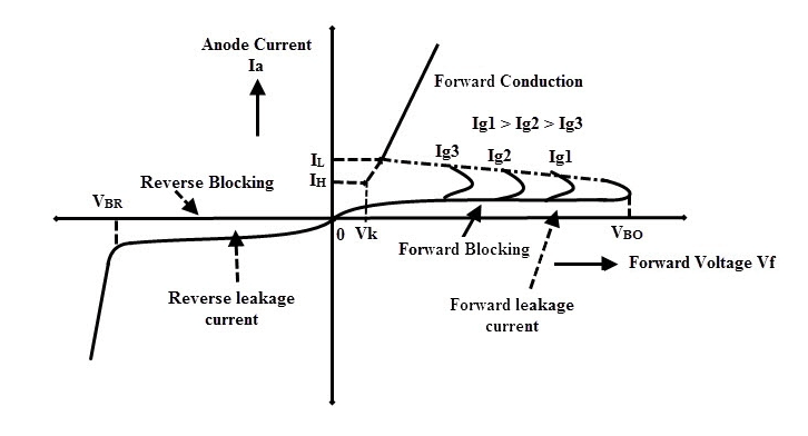
Figure 10: Flow through SCR
Forward Conduction Mode
In Forward Conduction Mode, the SCR conducts and operates in the ON state. This mode can be achieved by either increasing the forward bias voltage beyond the breakdown voltage or applying a positive voltage to the gate terminal. Increasing the forward bias voltage causes the junction to undergo avalanche breakdown, allowing significant current to flow. For low-voltage applications, applying a positive gate voltage is more practical, initiating conduction by making the SCR forward-biased. Once the SCR begins conducting, it remains in this state as long as the current exceeds the holding current (IL). If the current falls below this level, the SCR returns to the blocking state.

Figure 11: SCR Conduction
Reverse Blocking Mode
In Reverse Blocking Mode, the cathode is positive relative to the anode. This configuration allows only a small leakage current through the SCR, which is insufficient to turn it on. The SCR maintains a high impedance state and acts as an open switch. If the reverse voltage exceeds the breakdown voltage (VBR), the SCR undergoes avalanche breakdown, significantly increasing the reverse current and potentially damaging the device.
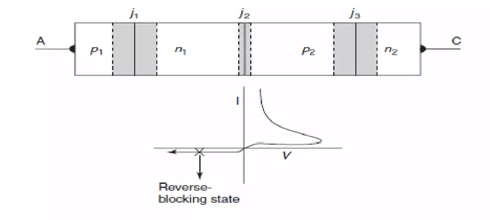
Figure 12; SCR Reverse Blocking Mode
Different Types of SCRs and Packages
Silicon Controlled Rectifiers (SCRs) come in various types and packages, each tailored for specific applications based on current and voltage handling, thermal management, and mounting options.
Discrete Plastic
Discrete Plastic packages feature three pins extending from a plastic-encased semiconductor. These economical planar SCRs typically support up to 25A and 1000V. They are designed for easy integration into circuits with multiple components. During installation, ensure proper pin alignment and secure soldering to the PCB to maintain reliable electrical connections and thermal stability. These SCRs are ideal for low to medium-power applications where compact size and cost efficiency are essential.
Plastic Module
Plastic Modules contain multiple devices within a single module, supporting currents up to 100A. These modules enhance circuit integration and can be bolted directly to heat sinks for improved thermal management. When mounting, apply an even layer of thermal compound between the module and the heat sink to enhance heat dissipation. These modules are suitable for medium to high-power applications where space and thermal efficiency are critical.
Stud Base
Stud Base SCRs feature a threaded base for secure mounting, providing low thermal resistance and easy installation. They support currents ranging from 5A to 150A with full voltage capabilities. However, these SCRs cannot be easily isolated from the heat sink, so consider this during thermal design to avoid unintended electrical connections. Follow proper torque specifications when tightening the stud to avoid damage and ensure optimal thermal contact.
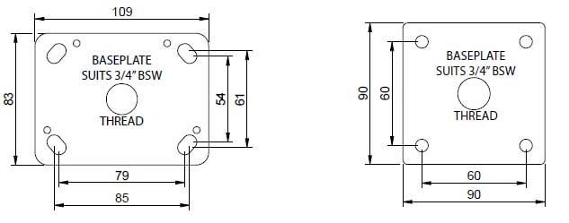
Figure 13: SCR Stud Base with Number Distance
Flat Base
Flat Base SCRs offer the mounting ease and low thermal resistance of Stud Base SCRs but include insulation to electrically isolate the SCR from the heat sink. This feature is crucial in applications requiring electrical isolation while maintaining efficient thermal management. These SCRs support currents between 10A and 400A. During installation, ensure the insulation layer remains intact and undamaged to maintain electrical isolation.
Press Pack
Press Pack SCRs are designed for high-current (200A and above) and high-voltage applications (exceeding 1200V). They are encased in a ceramic envelope, providing excellent electrical isolation and superior thermal resistance. These SCRs require precise mechanical pressure to ensure proper electrical contact and thermal conductivity, typically achieved using specially designed clamps. The ceramic casing also protects the device from mechanical stress and thermal cycling, making them suitable for industrial and high-power applications where reliability and durability are paramount.
Practical Operation Insights:
When working with Discrete Plastic SCRs, focus on precise pin alignment and secure soldering for stable connections. For Plastic Modules, ensure an even application of thermal compound for optimal heat dissipation. With Stud Base SCRs, follow torque specifications to avoid damage and achieve effective thermal contact. For Flat Base SCRs, maintain the integrity of the insulation layer to ensure electrical isolation. Lastly, with Press Pack SCRs, apply the correct mechanical pressure using specialized clamps to ensure proper contact and heat management.
Silicon Controlled Rectifier Opening Method
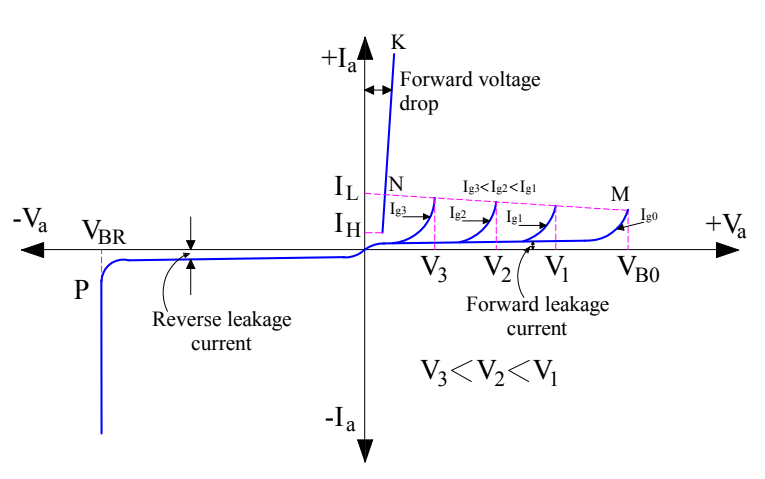
Figure 14: SCR Operation Turning ON
To activate SCR conduction, the anode current must surpass a critical threshold, which is achieved by increasing the gate current (Ig) to initiate regenerative action.
Begin by ensuring the gate and cathode are correctly connected to the circuit, verifying that all connections are secure to avoid any loose contacts or misconfigurations. Monitor both ambient and junction temperatures, as high temperatures can affect the SCR's performance, necessitating adequate cooling or heat dissipation measures.
Then, start applying a controlled gate current (Ig) using a precise current source, gradually increasing Ig to allow for a smooth transition and easy monitoring of the SCR's response. As Ig is gradually increased, observe the initial rise in anode current, indicating the SCR's response to the gate current. Continue to increase Ig until regenerative action is observed, marked by a significant rise in anode current, showing that the SCR is entering conduction mode. Maintain the gate current just enough to sustain conduction without overdriving the gate to prevent unnecessary power dissipation and potential damage. Ensure the appropriate voltage is applied between the anode and cathode, monitoring this voltage to avoid surpassing the breakover point unless intentionally required for specific applications.
Finally, confirm that the SCR has latched into conduction mode, where it will remain even if the gate current is reduced. If necessary, reduce the gate current (Ig) after confirming the SCR has latched, as it will stay in conduction until the anode current drops below the holding current level.
Silicon Controlled Rectifier Closing Method
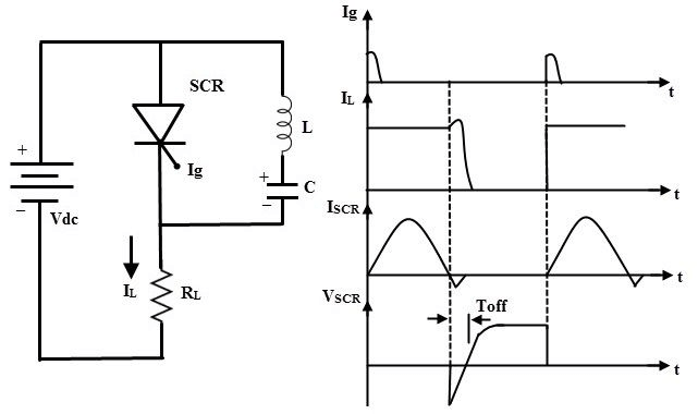
Figure 15: SCR Operation Turning OFF
Turning off a Silicon Controlled Rectifier (SCR) involves reducing the anode current below the holding current level, a process known as commutation. There are two primary types of commutation: natural and forced.
Natural Commutation occurs when the AC supply current naturally falls to zero, allowing the SCR to turn off. This method is inherent in AC circuits where the current periodically crosses zero. In practical terms, imagine an AC circuit where the voltage and current waveforms periodically reach zero. As the current approaches zero, the SCR ceases to conduct and turns off naturally without any external intervention. This is commonly seen in standard AC power applications.
Forced Commutation actively reduces the anode current to turn off the SCR. This method is necessary for DC circuits or situations where the current does not naturally fall to zero. To achieve this, an external circuit momentarily diverts the current away from the SCR or introduces a reverse bias. For example, in a DC circuit, you might use a commutation circuit that includes components like capacitors and inductors to create a momentary reverse voltage across the SCR. This action forces the anode current to drop below the holding level, turning off the SCR. This technique requires precise timing and control to ensure reliable operation.
Advantages of Silicon Controlled Rectifier
High Efficiency and Noiseless Operation
SCRs operate without mechanical components, eliminating friction and wear. This results in noiseless operation and enhances reliability and longevity. When equipped with proper heat sinks, SCRs efficiently manage heat dissipation, maintaining high efficiency across various applications. Imagine installing an SCR in a quiet environment where mechanical noise would be disruptive; the silent operation of an SCR becomes a significant advantage. Additionally, during extended operation, the absence of mechanical wear contributes to fewer maintenance needs and a longer lifespan.
Extremely High Switching Speed
SCRs can switch on and off within nanoseconds, making them ideal for applications requiring rapid response times. This high-speed switching allows for precise control over power delivery in complex electronic systems. For instance, in a high-frequency power supply, the ability to switch quickly ensures that the system can respond to changes in load conditions almost instantaneously, maintaining stable output.
Handling High Voltage and Current Ratings
SCRs require only a small gate current to control large voltages and currents, making them highly efficient in power management. They can manage high power loads, making them suitable for industrial applications where high voltage and current are common.
Compact Size
The small size of SCRs allows for easy integration into various circuit designs, enhancing design flexibility. Their compact and robust nature ensures reliable performance over long periods, even in demanding conditions. In practical terms, this means that in a densely packed control panel, SCRs can be easily fitted without requiring significant space, allowing for more streamlined and efficient designs.
Disadvantages of Silicon Controlled Rectifier
Unidirectional Current Flow
SCRs conduct current only in one direction, making them unsuitable for applications requiring bidirectional current flow. This limits their use in AC circuits where bidirectional control is necessary, such as in inverter circuits or AC motor drives.
Gate Current Requirement
To turn on an SCR, a sufficient gate current is required, necessitating additional gate drive circuitry. This increases the complexity and cost of the overall system. In practical applications, ensuring the gate current is adequately supplied involves precise calculations and reliable components to avoid triggering failures.
Switching Speed
SCRs have relatively slow switching speeds compared to other semiconductor devices like transistors, making them less suitable for high-frequency applications. In high-speed switching power supplies, for example, the slower switching speed of SCRs can lead to inefficiencies and increased thermal management requirements.
Turn-Off Time
Once turned on, SCRs remain conducting until the current falls below a certain threshold. This characteristic can be a disadvantage in circuits where precise control of the turn-off time is required, such as in phase-controlled rectifiers. Operators often need to design complex commutation circuits to force the SCR to turn off, adding to the overall system complexity.
Heat Dissipation
SCRs generate significant heat during operation, especially when handling high currents. Adequate cooling and heat dissipation mechanisms, such as heatsinks and cooling fans, are necessary.
Latching Effect
After an SCR is turned on, it latches into the conducting state and cannot be turned off by the gate signal. The current must be externally reduced below the holding current to turn off the SCR. This behavior complicates control circuitry, particularly in variable load applications where maintaining precise control over current levels is essential. In such scenarios, engineers must design circuits that can reliably reduce the current when needed to turn off the SCR.
Commutation Requirements
In AC circuits, SCRs need to be commutated (turned off) at the end of each half-cycle, requiring additional commutation circuits, such as resonant circuits or forced commutation techniques. This adds complexity and cost to the system.
Sensitivity to dv/dt and di/dt
SCRs are sensitive to the rate of change of voltage (dv/dt) and current (di/dt). Rapid changes can inadvertently trigger the SCR, necessitating the use of snubber circuits to protect against such events. Designers must ensure snubber circuits are properly sized and configured to prevent false triggering, especially in noisy electrical environments.
Noise Sensitivity
SCRs can be sensitive to electrical noise, which might cause false triggering. This requires careful design and additional filtering components, such as capacitors and inductors, to ensure reliable operation.
Conclusion
Understanding SCRs involves examining their symbols, layer compositions, terminal connections, and material choices, highlighting their precision in managing high currents and voltages. Different SCR packages, from Discrete Plastic to Press Pack, cater to specific applications, emphasizing proper installation and thermal management. The operational modes—forward blocking, forward conduction, and reverse blocking—illustrate their capability to regulate power in various circuit configurations. Mastering SCR activation and deactivation techniques ensures reliable performance in power control systems. The high efficiency, rapid switching, and compact size of SCRs make them essential in both industrial and consumer electronics, representing significant advancements in power electronics.
Frequently Asked Questions [FAQ]
1. What is silicon-controlled rectifier (SCR) used for?
An SCR is used to control power in electrical circuits. It acts as a switch that can turn on and off the flow of electrical current. Common applications include regulating motor speed, controlling light dimmers, and managing power in heaters and industrial machinery. When an SCR is triggered by a small input signal, it allows a larger current to flow through, making it effective in high-power applications.
2. Why is silicon used in SCR?
Silicon is used in SCRs because of its favorable electrical properties. It has a high breakdown voltage, good thermal stability, and can handle high currents and power levels. Silicon also allows for the creation of a compact and reliable semiconductor device that can be precisely controlled.
3. Is SCR control AC or DC?
SCRs can control both AC and DC power, but they are more commonly used in AC applications. In AC circuits, SCRs can control the phase angle of the voltage, thereby adjusting the power delivered to the load. This phase control is essential for applications like light dimming and motor speed regulation.
4. How do I know if my SCR is working?
To check if an SCR is working, you can perform a few tests. First, visual inspection. Look for any physical damage, such as burns or cracks. Then, use a multimeter to check the forward and reverse resistance. An SCR should show high resistance in reverse and low resistance in forward when triggered. Next, apply a small gate current and see if the SCR conducts between the anode and cathode. When the gate signal is removed, the SCR should continue conducting if it's functioning correctly.
5. What causes SCR failure?
Common causes of SCR failure are overvoltage, overcurrent, gate signal issues and thermal stress. Excessive voltage can break down the semiconductor material. Too much current can cause overheating and damage the device. Repeated heating and cooling cycles can cause mechanical stress and lead to failure. Improper or inadequate gate signals can prevent proper operation.
6. What is the minimum voltage for SCR?
The minimum voltage required to trigger an SCR, called the gate trigger voltage, is typically around 0.6 to 1.5 volts. This small voltage is enough to turn on the SCR, allowing it to conduct a much larger current between the anode and cathode.
7. What is an example of a SCR?
A practical example of an SCR is the 2N6509. This SCR is used in various power control applications, such as light dimmers, motor speed controls, and power supplies. It can handle a peak voltage of 800V and a continuous current of 25A, making it suitable for industrial and consumer electronics.
 ABOUT US
Customer satisfaction every time. Mutual trust and common interests.
function test. The highest cost-effective products and the best service is our eternal commitment.
Hot Article
- Are CR2032 and CR2016 Interchangeable
- MOSFET: Definition, Working Principle and Selection
- Relay Installation and Testing, Interpretation of Relay Wiring Diagrams
- CR2016 vs. CR2032 What’s the difference
- NPN vs. PNP: What's the Difference?
- esp32 vs stm32: which microcontroller is better for you?
- LM358 Dual Operational Amplifier Comprehensive Guide: Pinouts, Circuit Diagrams, Equivalents, Useful Examples
- CR2032 VS DL2032 VS CR2025 Comparison Guide
- Understanding the Differences ESP32 and ESP32-S3 Technical and Performance Analysis
- Detailed Analysis of RC Series Circuit
 A Comprehensive Guide to Fuses and Their Functions
2024-05-24
 H7 vs. H8 Batteries: The Ultimate Guide to Choosing the Right Power Source for Your Vehicle
2025-03-31
Hot Part Number
 UVR2C4R7MED1TD
 GRM022R60J223ME15L
 C0402C0G1C8R2D
 CL21B681KBANNNC
 CGA9L1X7S3A223K160KA
 GRM0335C1E6R9DA01D
 CC0402MRX7R7BB223
 LD051C273KAB2A
 08055C103KAQ2A
 1812HA151KAT1AJ
- T495D157K016ATE085
- TLJR476M004R3000
- TAJD227K004RNJ
- SM15T68CA
- ATF22LV10C-15SI
- IS46TR16640A-15GBLA1
- VI-2NY-EU
- PIC18F26J50T-I/SO
- CM1000HC-66H
- ADS8507IDWR
- S99-50031
- RT0805DRE074R99L
- T491C107K010ATAU53
- ADC08D500CIYB
- EDS6416AHTA-75-E
- EM256C08N
- GBU1506
- LC75412EH
- M34236MJ214GP
- MAX8213AESE
- MAX884CSA
- MB89191APF-G-293-ER-RE1
- MC34114DW
- MC74HC08AF
- MST30HA3-LF
- SAA7705H/303
- SPHE8104TW-C-HL117
- TMP87C840F-4836
- TSC80251G1D-24CB
- DRH407BIZDUQ1
- K4E6E304EB-AGCF
- MTS142LG-B0-R
- SED1330FBA
- TUSB8042AIRGCR
- DRV8906QPWPRQ1
- M38022M4-001FP
- SR1641ACB4YZR
- CXP5086-729Q
- P78E15-1000